


Upcoming Events

Tradeshows | Apr 29 - 02, 2024 | Galveston, US
REFCOMM 2024
Join the Flowserve team at RefComm 2024, the world’s leading technical conference for the refinery industry, from May 8–12 in Galveston, Texas.

We help make the world better – together
Culture at Flowserve

We are inspired by our purpose
With six core values at the heart of everything we do, making the world better extends beyond our flow control solutions.
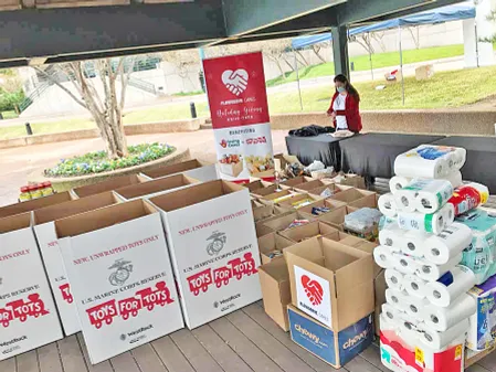
Making an impact in our communities

Introducing our refreshed ESG approach